Abstract
For our final project, we created an OpenGL video game. The game is a first person 3D maze in which the player tries to navigate to the maze’s exit. The maze is procedurally generated and consists of three different wall types: opaque walls, mirror walls, and glass walls. There are also 5 powerups that are randomly placed throughout the maze that give the player the following abilities: viewing the maze from a bird's-eye view, highlighting glass walls, highlighting mirror walls, turning mirror walls opaque, and turning glass walls opaque.
Technical approach
Maze generation
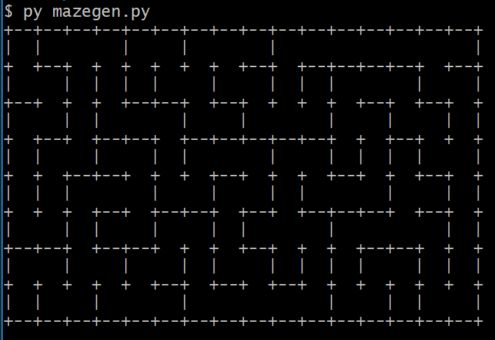
The maze is procedurally generated using a Python script that runs the following DFS algorithm:
- Starting with a grid of individually walled-off cells, the algorithm randomly traverses through the cells, removing walls as it goes. It stops the traversal when a cell has no unvisited neighbors (i.e. a dead end has been reached).
- Upon reaching a dead end, the algorithm backtracks until there is a cell with an unvisited neighbor and continues traversing from there.
- The process is repeated until all cells have been visited.
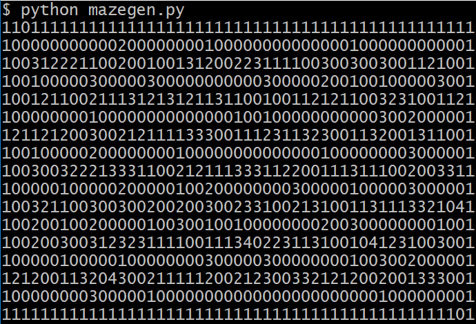
The source code has been modified in the following ways:
- Corridors are represented by a 0, opaque walls by a 1, mirror walls by a 2, and glass walls by a 3.
- The boundaries of the maze are always made of opaque walls; otherwise, a wall has a 1/2 chance of being opaque, 1/4 of being a mirror, and 1/4 chance of being glass.
- An entrance and exit have been added to the maze.
- There are 5 powerups in the maze. The algorithm randomly places 4 of them, which are represented by 4's.
- The first powerup is always located at the entrance of the maze, so it is not randomly placed by the maze generation algorithm.
|
|
The next step was integrating this Python script with the rest of our C++ code. The main C++ file calls the Python script, which writes its output into a text file. In the C++ file, the text file is read and converted into 3D coordinates of where the walls/powerups will be placed in the scene. Additionally, there is an array that stores the type of each wall so the appropriate shader effect (opaque/mirror/glass) is applied when the walls are rendered.
First-person camera movement
The matrix representing the view/camera space is derived from the following vectors: the camera position, the camera direction, the right axis, and the up axis. Given the position, direction, and up vectors, GLM's lookAt function creates this matrix for us. By modifying the camera position by a constant distance scaled by some speed every time a direction key <WASD> is pressed, we create the "walking around" effect of the camera. The "looking around" effect of the mouse is created by making use of the pitch and yaw Euler angles. This is accomplished by finding the offset of the mouse's position from the last frame from which the pitch and yaw is derived, constraining the pitch values, and calculating the direction vector.
|
|
Wall/item collisions and powerups
We modified the camera code to accept the wall/powerup positions and sizes as inputs. After the camera movement step has been calculated, we check if the new camera position intersects any of the walls or powerups. If it does, then the camera position reset to its original position plus a small bounce factor, which produces the effect of the player being pushed back by the object.
The powerup pickup algorithm is implemented in a similar manner. When the player presses "E," we check if the camera position is sufficiently close to a powerup. If it is, then the nearest powerup to the player is removed from the scene.
Key presses are tracked with booleans. Depending on the number of powerups the player has picked up, certain keys toggle the following effects:
- First powerup: "Y" for bird's-eye view.
- The camera position is set to a fixed point above the maze. The player can look around with the mouse, but normal movement with "WASD" is not allowed.
- Second powerup: "I" to highlight glass walls.
- When rendering, glass walls are rendered with a modified shader that darkens their appearance.
- Third powerup: "U" to highlight mirror walls.
- When rendering, mirror walls are rendered with a modified shader that brightens their appearance.
- Fourth powerup: "J" to turn mirror walls opaque.
- When rendering, mirror walls are rendered with the same shader as opaque walls.
- Fifth powerup: "K" to turn glass walls opaque.
- When rendering, mirror walls are rendered with the same shader as opaque walls.
Shaders/Textures for the maze environment
All vertex shaders used for the walls and powerups take in view, model, and projection uniform matrices which are used to map from object space to screen space.
The shaders used for the powerup items are similar to the starter code for the extra credit portion from Project 3-2, Part 5. The color is calculated in the vertex shader as a sin/cos function of time. The same color is passed into the fragment shader, which simply outputs it. The rotation of the powerup is calculated in a similar manner based on time. A rotation matrix calculated in the main C++ file. First, a spin is calculated based on the time; this is used as an Euler angle, converted into a quaternion, and finally converted to a 4x4 matrix. This matrix is passed into the vertex shader as a uniform, which then applies the rotation matrix to the position of the vertex.
The opaque walls use fairly basic texture mapping. The texture coordinates are mapped onto a corresponding vertex on the 3D object. The color of the walls are slightly altered from the original texture by adding a constant value to the output color in the fragment shader.
The background, mirror walls, and glass walls all make use of cubemapping. A cubemap is composed of 6 textures that form a cube that completely captures an environment in all directions.
The background is a skybox: a cube that encompasses the entire scene. The cubemap is mapped onto this giant cube and gives the illusion that the player is in a large environment. The shaders are fairly straightforward, the one point of note being that the position vector passed into the vertex shader is then output as the texture coordinate passed to the fragment shader. For optimization purposes, the skybox is rendered last, which is possible by setting it at maximum depth.
The mirror and glass walls make use of environment mapping of the cubemap. In the reflection fragment shader for the mirror effect, the vector from the view/camera position to the object is calculated and reflected across the surface normal; the skybox is then sampled in the direction of the reflected vector for the final output fragment color. Similarly, the refraction fragment shader refracts the vector according to the ratio of the index of refraction (in the case of glass, 1.00 / 1.52) and samples the skybox for color accordingly.
To produce the highlighting effects of the powerups, the reflection and refraction fragment shaders are modified to alter the color output of the fragment. This is achieved by adding/subtracting a constant value to the output color.
|
|
||
|
|
|
|
Laser
See below in the Challenges section for more details.
Challenges
Setting up and integrating code
A major obstacle we encountered during the project was setting up OpenGL and all the necessary packages/dependencies in Visual Studio. This was especially frustrating when team members were working on separate parts of the project, and we would encounter countless errors due to missing dependencies/files when attempting to integrate code. One of our team members had additional difficulties in getting Visual Studio set up properly on her Mac. Once we finally sorted out all the packages and files we would need to proceed with the rest of the project, the process became much smoother.
The learning curve for using Visual Studio as a C++ IDE as well as becoming accustomed to OpenGL and all its packages was also very steep. The majority of our first 2-3 weeks was spent with set up and going through basic tutorials.
Dynamic environment mapping
The mirror and glass walls in the maze do not display the other objects in the maze in their reflections/refractions because the shaders use the cubemap of the environment, which does not contain those objects in its textures. In trying to include the other objects in the reflections, we looked into dynamic environment mapping, which dynamically generates cubemaps of the scene as its being rendered. However, this process is extremely computationally intensive, since a cubemap must be rendered for each reflective/refractive object for it to look correct; in other words, the entire scene must be rendered 6 times per object. One potential workaround is pre-rendering cubemaps; however, our maze environment is randomly generated, so pre-rendering was not an option. Ultimately, we decided to retain the basic environment mapping of the skybox.
Laser
We originally intended to implement a laser pointer that would follow the camera movement of the player which would help the player distinguish between mirror and glass boxes by the reflection/refraction of the laser. We faced many difficulties when attempting to implement it and were ultimately unable to make it a part of our final project.
Our first idea for implementing a laser was to draw a simple line whose appearance we could later modify with textures; however, we found that modern versions of OpenGL (like the one we are using) no longer supports line drawing capabilities. We then found other resources for implementing lasers in OpenGL. The source code used a different package (GLEW) than the one we had been using for the rest of the project (GLAD), which caused a lot of integration issues.
The original source code we built off of rendered three lasers, defined by their starting and ending points, that could be viewed from any angle. We were able to modify the source code to allow the player to control the starting and ending position of the laser. We were also able to simulate the laser bouncing off a reflective surface by reflecting the laser across the surface normal; lasers also pass through glass surfaces.
In our attempt to integrate the code into our project, we set one laser with its starting and end point placed in front of the camera. Orthographic matrices are then applied to those vertices to project the laser onto screen space; as a result, the laser is fixed at a constant location on the screen. We were able to have the laser change size and position on the screen as a result of camera movement by passing in the camera's location as the parameters into the orthographic matrix constructor. However, we were unable to make these changes relate to camera movement in a natural way (i.e. interacting with objects in the world), since the source code we relied on began by projecting the laser coordinates to a viewPort and then modifying the location in the two dimensional space, and we were unable to undo those applications in the time we had left after figuring out how to combine the relevant OpenGL packages in the same file without erroring out. As a result, the laser is not included in our final submission.
|
|
Lessons learned
The main lesson we learned is that graphics is difficult, even with established packages and utilities, but highly rewarding. While the process of setting up the project, linking all the packages together, getting past the learning curve for OpenGL, and integrating different parts of code was frustrating, being able to see and play with our final results made the effort worth it.
On the more technical side, we learned the power of OpenGL and its ability to render in real-time, as well as the flexibility of shaders in changing the appearance of objects and the viewing perspective of the rendered scene. We also reinforced physics concepts learned in class, such as reflection and refraction for mirror/glass objects, the behavior of light with such objects, and detecting collisions and intersections.
Results
|
|
|
|
|
|
|
|
|
|
|
|
References
- Setting up Visual Studio, OpenGL, GLFW, GLAD
- Maze generation code
- Project 3-2, Part 5
- OpenGL tutorial
- Cubemap source
- Cubemap reflections tutorial
- Rendering to cube map texture tutorial
- Lasers: Video demo + high level overview
- Lasers: High level overview
- Simple laser implementation
- Screen recording app
Contributions
|
Sonty |
Julie |
Varsha |
|
|
|
Miscellaneous Links
- Project Webpages
- Milestone Materials
- Final Materials